Read a fascinating first hand account of the development and first use of trolley modules by the originator of our standards, Everitt F. Wood.
The East Penn Traction Club has been a pioneer in the modular concept, pre-dating some of the more well known modular efforts existing today. Our approach capitalizes on the unique requirements for model trolley operation and scenery and is based on a truly modular approach (as opposed to a sectional layout approach). This approach differs significantly in several key areas from other standards, specifically:
At present, the East Penn standards (or variations thereof) are in use on more trolley modules than any other standard. While most are concentrated in the northeastern United States, many can also be found in other parts of the country.
In September 1969, Everitt F. Wood (former Chairman of the National Model Railroad Association's Traction Committee) published HO scale and O scale designs for model trolley layout modules in Traction and Models magazine. His purpose was to set forth bare minimum requirements for two track sections. Modelers could individually build and then collectively assemble these modules in any arrangement at modelers' meets or public shows.
The Magee Transportation Museum Trolley Meet in Bloomsburg, Pa. in May, 1970, featured the first layout of modules built to Wood's design. These O scale sections had track ranging from handlaid scale rail up to Gargraves tinplate track, yet they all worked together. Modular layouts have been a focal point at trolley meets ever since. Since the introduction of modules, layouts larger than home layouts and with a different track plan at every event have replaced compromised portable layouts that were small by necessity.
Modules can be any size, but a 48 inch length has been typical. Simple leg assemblies slip between adjoining modules, and long bolts passing through oversize holes hold everything together. With this design, modules with varying construction accuracy and rail stock of different sizes can be joined. Simply butting the rails together, without transition track sections or rail joiners, has proven to be operationally reliable. It also facilitates modeling paved street trackage. Track and overhead trolley wire construction follows applicable NMRA standards and recommendations, as well as common model trolley standards from the former Wagner Car Company.
Not many years later, Wood's minimalist standards were revised by the East Penn Traction Club, under the guidance of John T. Derr, on the basis of operating experience (Traction & Models, September 1974). The revisions were limited in scope, and in most cases existing modules built to the original standards could be upgraded. The changes included lengthening the legs from 32 inches to 36 inches. The HO track spacing was changed from 1.8 inches to an even 2 inches. The original two jumper wires, screwed to terminal blocks to carry rail and trolley wire power between modules, were replaced by 6-wire cables with connectors for faster set-up, easier control of close-headway operations, and easier fault isolation. Each track's rail and overhead wire is now electrically insulated from the other track on the module and from adjoining modules.
Today the East Penn module standards are in their third decade of use by trolley modelers from New England to Florida and at least as far west as Minnesota. Using end loop, turnback loop, yard, curve and junction modules built by creative modelers, complex layouts have been assembled and operated that offer running distances scale miles long and a choice of routes. Potentially dozens of cars can be kept moving simultaneously. Every convention layout's design depends on who brings modules, and each is unique in shape, arrangement and content. Many home layouts now have modules grafted to them, or are built of modules entirely.
The module standards of the East Penn Traction Club continue to offer trolley modelers enjoyable and diverse possibilities for design, construction, scenery and operation, without imposing a burden of extraneous restrictions and requirements.
Richard D. Kerr - Chairman, East Penn Module Standards Committee
Note: The drawings included with the on-line standards are high resolution bitmaps. They are provided for on-line reference only and are best viewed using a high resolution (SVGA or greater) device. To obtain printed copies of the drawing, download and print the standards document in Adobe .pdf format.
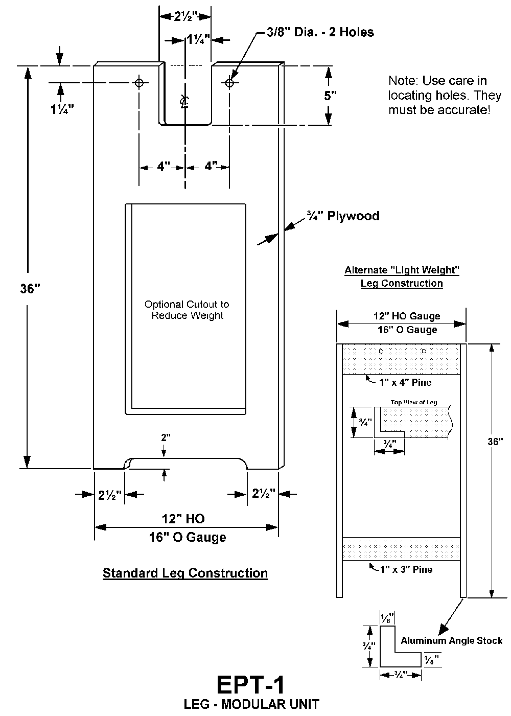
Legs: Drawing EPT-1 shows the standards for module leg design. A leg should be built and provided for each module. The standard material used to construct the legs is 3/4" plywood. Legs made of plywood are heavier, helping to stabilize the modules, and are uniform in appearance, especially if painted a uniform color. The thickness of the legs is a critical dimension, affecting the fit of joined modules and the size of the rail gaps between them. Legs can also be made using dimensional lumber which is exactly 3/4" thick, but care must be used, as an over thickness can cause wide gaps in the rail ends. Newer plywood should be checked to ensure it measures exactly 3/4" in width. Note that 3/4" x 3/4" aluminum angle can also be used to make very light weight legs, per drawing EPT-1.
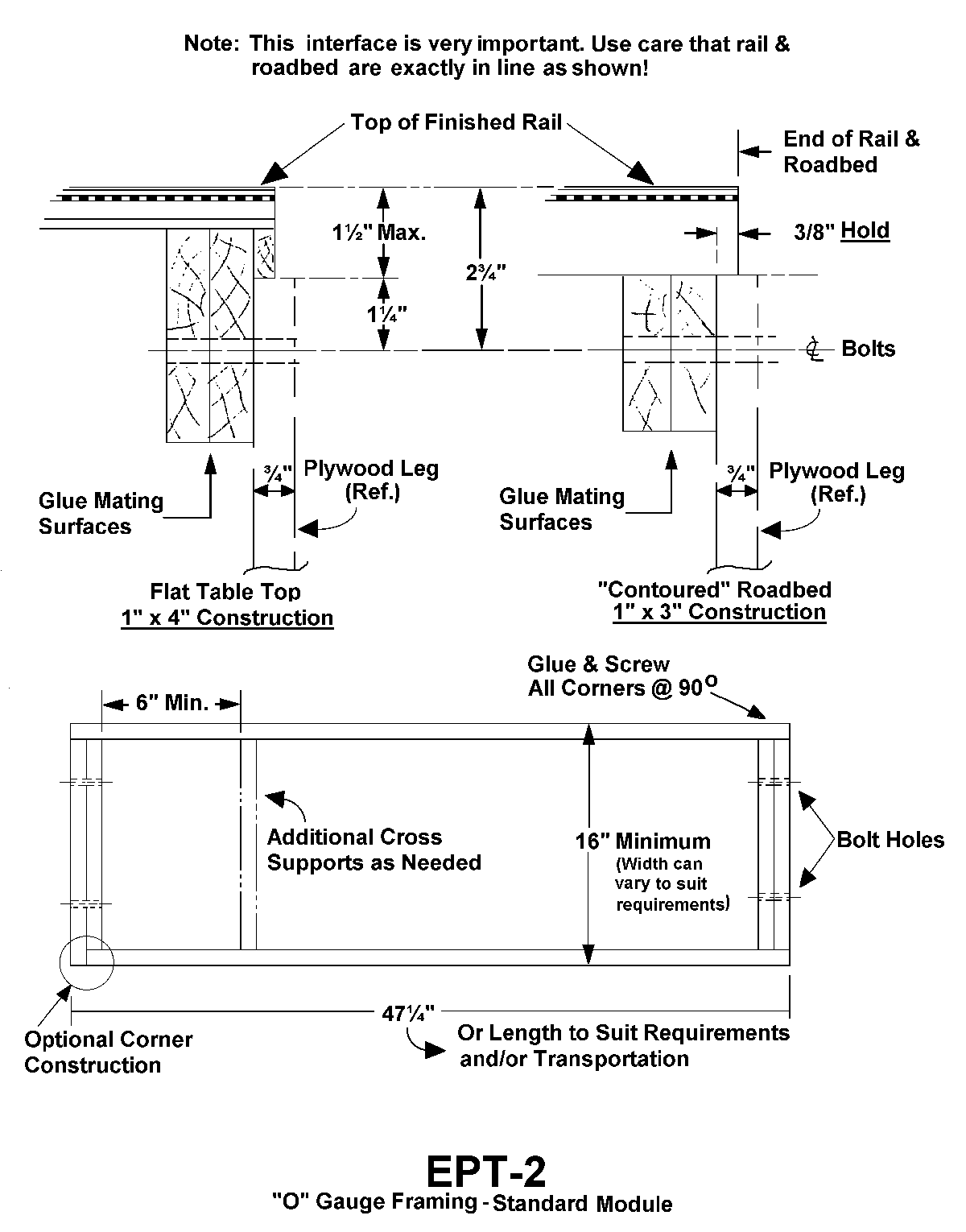
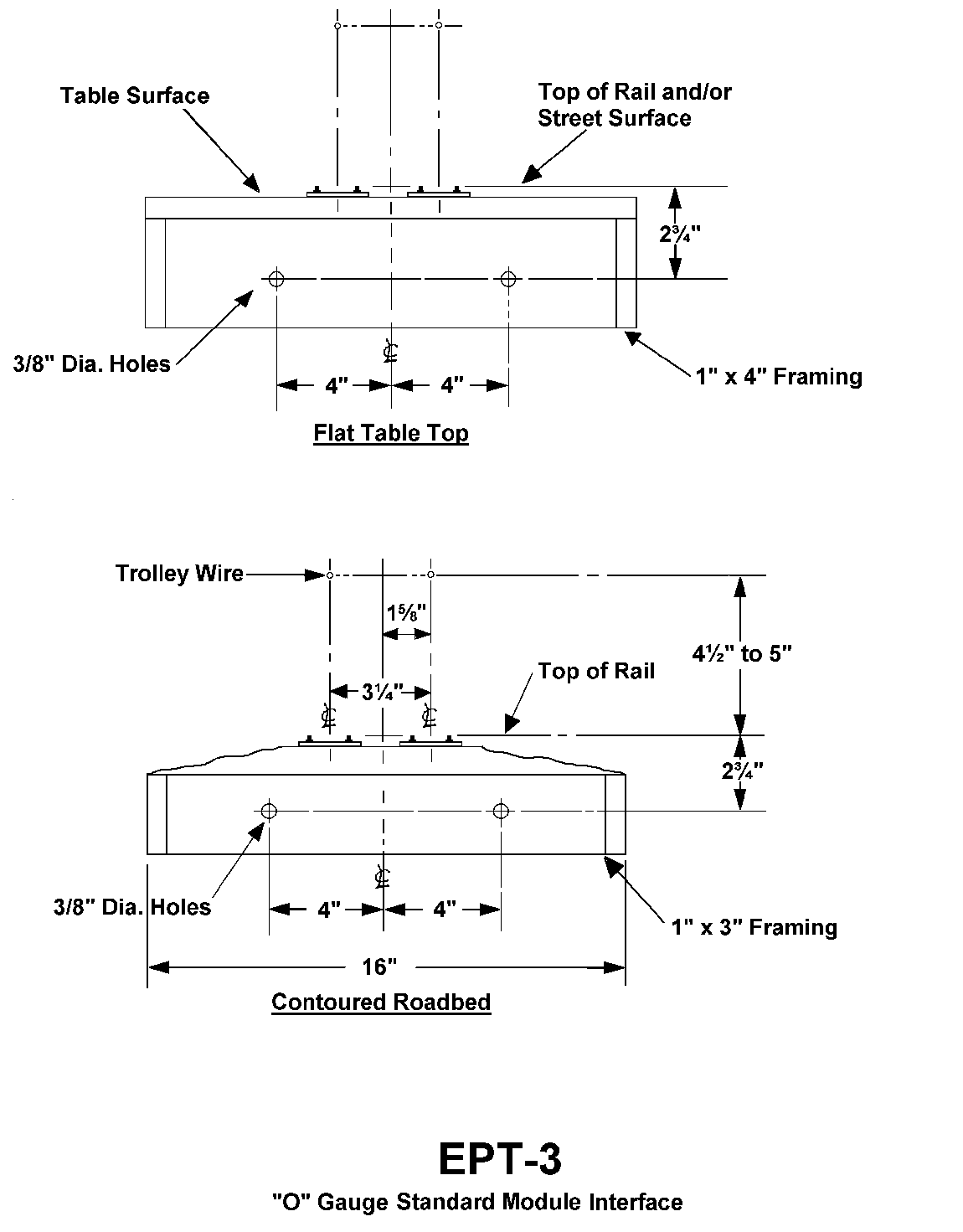
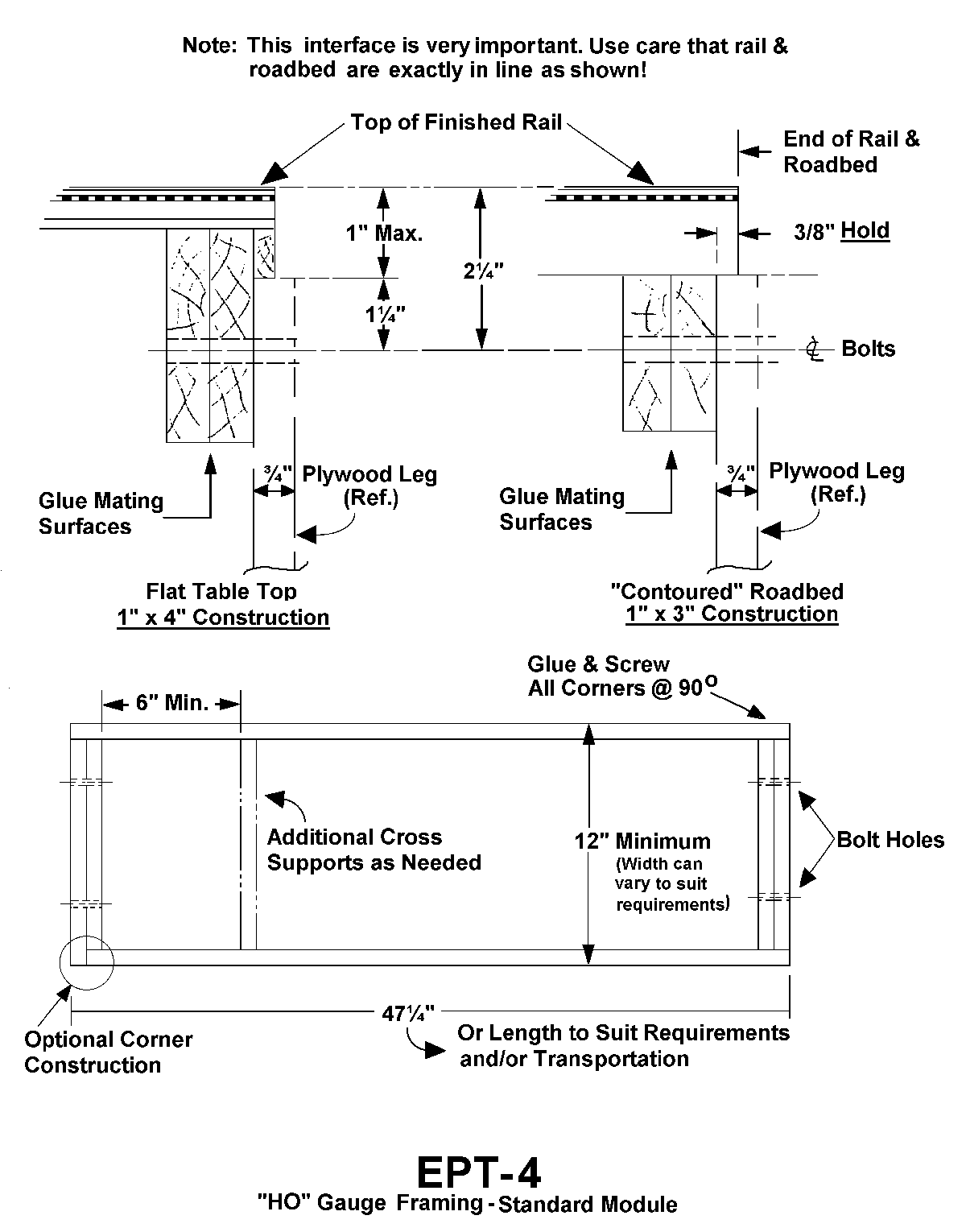
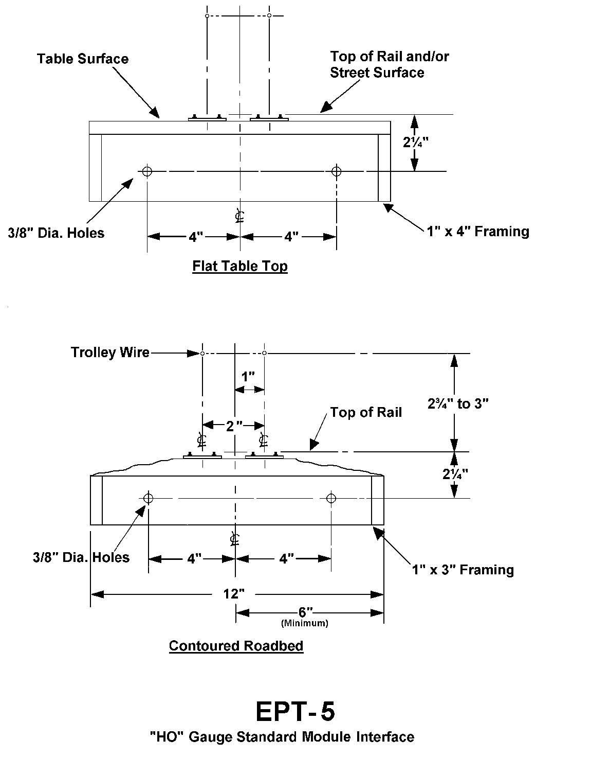
Framework: Drawings EPT-2 and EPT-3 show the basic framework and track standards for O scale; for HO scale see drawings EPT-4 and EPT-5. All wood for framing is suggested to be Commercial #1 grade pine, either 1" x 3" or 1" x 4" according to the type of module under construction. Other lumber can be substituted as long as it is straight grained and free from loose knots. Sides constructed of 3/8" plywood or 2" extruded foam insulation board (blue or pink type), properly braced and reinforced, have been used to save weight. The method and type of roadbed construction is optional. Pine, plywood, Homosote, and combinations thereof have been used, depending on the finished rail appearance desired. The distance between the end bolt holes and the top of rail is critical. So is the 3/8" end framing recess for the leg, and the distance between the bolt holes and the vertical centerline. Hex head bolts (1/4"-20, 5" long) with a flat washer at each end and a wingnut are used to bolt modules together, with the leg unit sandwiched between the modules. The hex head is very useful when more than hand tightening is needed. The oversize bolt holes allow some final track alignment before tightening the bolts firmly.
Trackwork: The weight and type of rail is optional, although Code 125 rail (0.125" high) is most common in O scale and Code 70 or commercial girder rail (Richard Orr) in HO. Since the location of the bolt holes is measured from the top of rail, modules with differing rail sizes can be mated together. The minimum radius of track curves, a prototypical 50 feet, is defined as 12 1/2" in O scale and 7" in HO scale, to center of track. Wider radius curves are preferred. The maximum grade is 10 percent. The first 2" of track from any module interface end must be flat and straight. Track gauge and spacing to centerline obviously are critical dimensions. Rails should end flush with the module interface, avoiding contact or excessive gaps with the adjoining module's rail.
Overhead: Poles to support the overhead trolley wire are placed 4" to 8" from each module interface end in O scale, and 2" to 3 1/2" in HO scale. For portability, a short, expendable piece of overhead wire is used to bridge the gap between modules. To properly insulate the modules, the overhead wire must also have an insulator on each "outbound" section of overhead. The traditional mechanism for achieving these requirements is the use of small plates in which four #60 holes have been drilled (see drawing EPT-8) and which are attached to the end of the overhead wire at the module boundaries. The two holes spaced 1/16" or less apart are for the overhead wires, and the other two are for the span wires. These plates are brass on each incoming track end, and 1/32" or 3/64" thick fiberglass (to serve as an insulator) on each outgoing track end. The overhead wires for the two basic tracks on the module must be insulated from each other. Again, fiberglass pieces can be used in the span wires to insulate the two track wires, and in the overhead wire itself, as needed, to divide it into local control block sections.
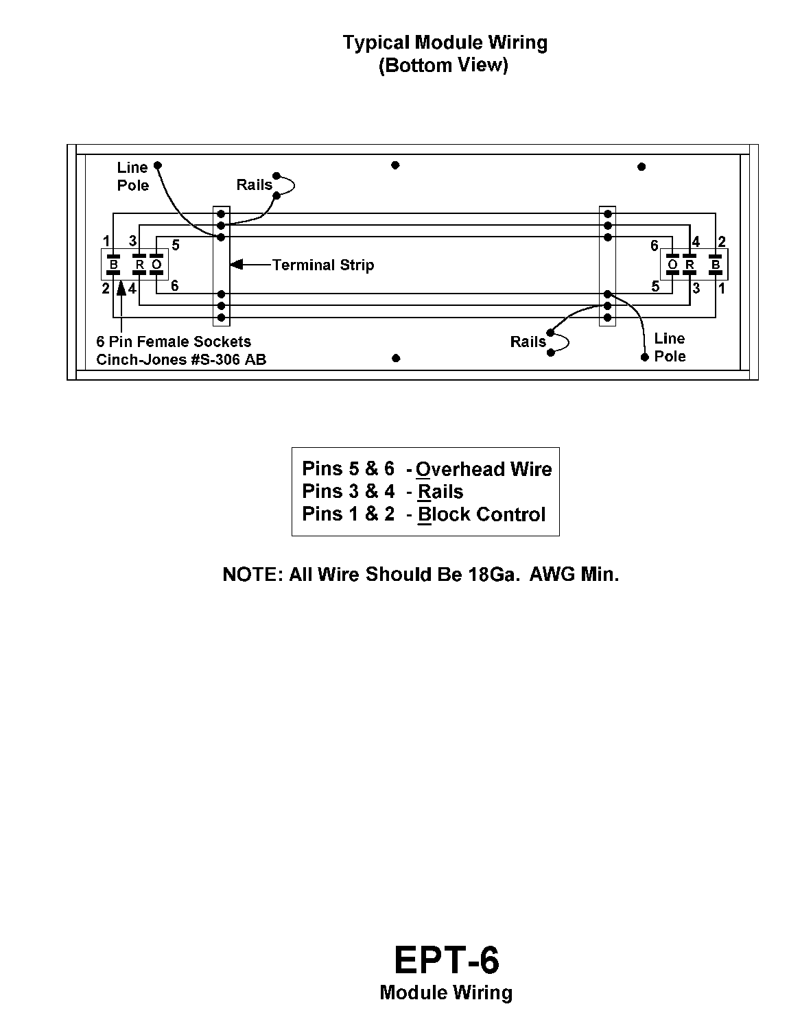
Wiring: Six buss wires, 18 Ga. AWG size minimum, run between terminal blocks under each end of the module, where cable sockets mounted under each end are also connected. There is one wire to conduct each track's rail current, one for each track's overhead wire current, and the remaining two wires are used for remote block control of the tracks on a distant module. A module's internal rail and overhead wire connections are made to the appropriate buss wires; overhead wire or rail must not be the sole conductor through a module. Drawing EPT-6 shows the typical wiring for a simple module.
The standards provide for each track to be electrically insulated from each other, thereby making it feasible to use a separate controller for each track. The East Penn Traction Club has never found it necessary to do so, but the capabilities for dual control are accommodated in the standard.
Connectors: Electrical connections between modules are made by six-pin plugs and sockets, which are used to make set-up easier. The plug is Cinch-Jones P-306 CCT and the socket is S-306 AB, or their interchangeable equivalents made by other firms. A socket is mounted under each interface end of a module. The Club keeps a supply of these connectors in inventory and makes them available to members at cost. Contact the current club secretary for information.
The wiring of the connectors is simple. If the socket is held inverted as it would be when mounted underneath, the six wiring prongs are now upward and in line with the module length. The three prongs on each side are used for the track on that side. It is important to note the uneven spacing of the prongs. Always mount the socket so that pins 1 and 2, the ones spaced farther apart, are toward the end of the module. Wire the rails (ground) to pins 3 and 4, the center pins. The overhead wires connect to pins 5 and 6. The use of pins 1 and 2 is discussed below.
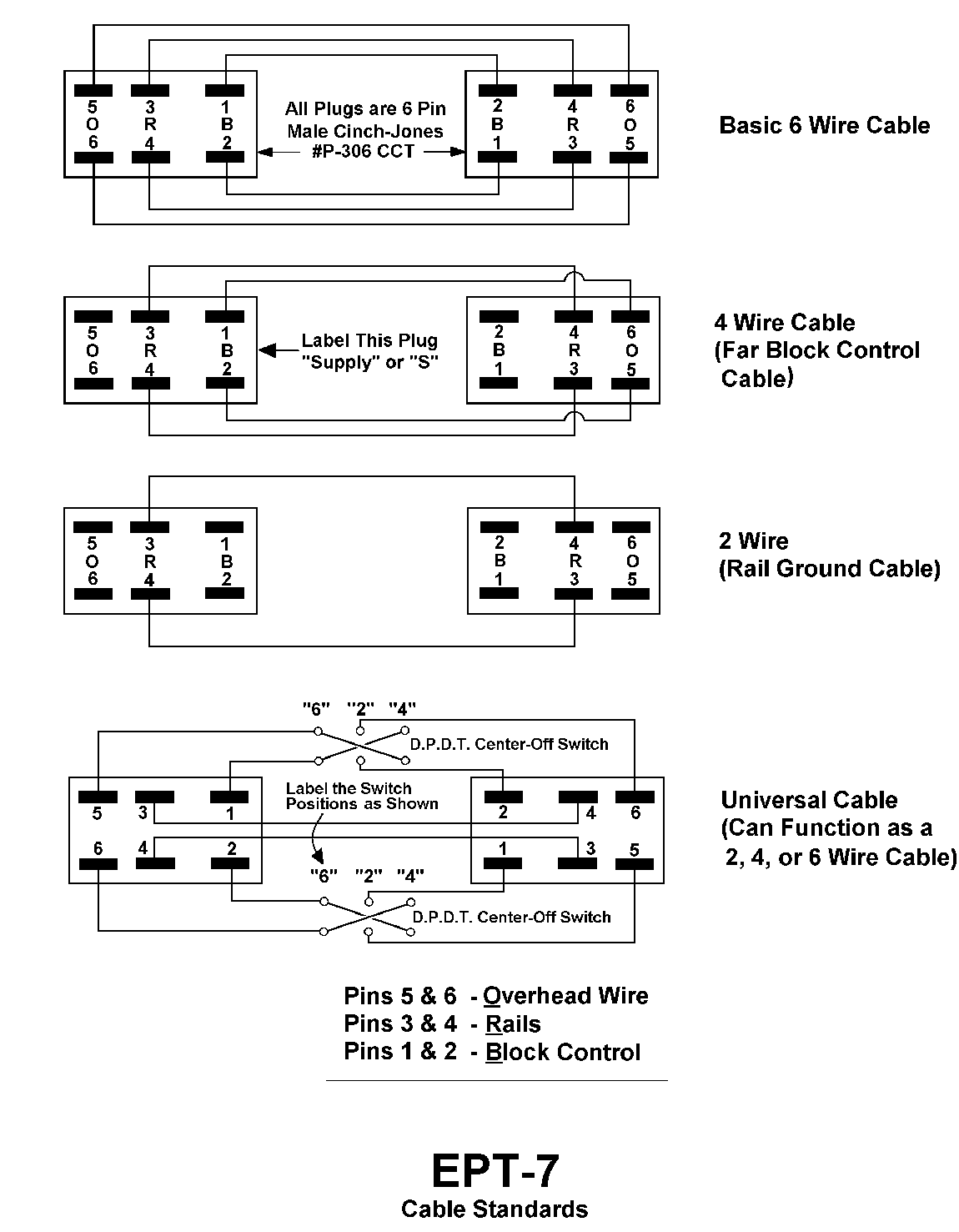
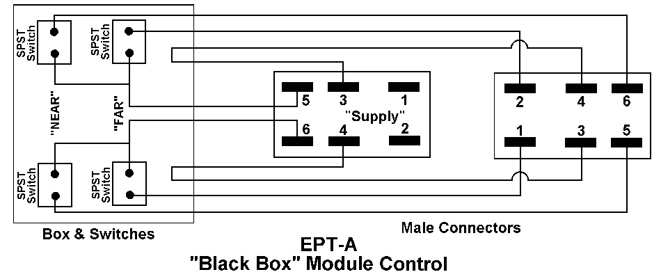
Cables: The cabling system makes it possible to control the power fed to each track of two remote modules at each interface, allowing for close-headway operations. A short cable, approximately 18" long, with a plug at each end, passes through the leg and connects the modules. Drawing EPT-7 shows a basic cable, the special 2 and 4 wire cables, and a universal cable that serves any of the cabling needs discussed here. Drawing EPT-8 shows part of a typical layout set-up. A module with a control panel should provide four extra toggle switches for each interface end. Two of these switches feed overhead wire power to socket pins 5 and 6 at that interface, controlling each track of the adjoining module ("Near Block"). The other two switches feed overhead wire power to socket pins 1 and 2, used to remotely control each track of a second module ("Far Block"). This second module is connected by a special four-wire cable, which carries the rail ground wires between pins 3 and 4, but cross-wires pins 1 and 2 on the supply-end plug to pins 6 and 5 on the other plug. Lastly, at the dividing point between sections controlled by different operators, a two-wire cable connects just the rail ground pins 3 and 4. (See Appendix A and drawing EPT-A for details on how to add control capabilities to an existing or non-control module using a 'Black Box'.)
General: Painting the modules is optional, but recommended for appearance. East Penn has adopted a medium tan for the module framework and a dark brown for the legs. The permanently joined ends of pieces which comprise a large module need not meet the interface requirements. A module must supply its own power for track switches, signals, lights, or other accessories. Each module should be accompanied by a leg, a cable, bolt sets and a multi-outlet extension cord.
[Module Standards and Drawings by: John T. Derr, Tom O'Donnell, and Richard D. Kerr. Universal cable and "black box" designs by Richard D. Kerr. Alternate leg design by Barbara Brody. Drawings digitally rendered by Gary M. Reighn.]
© Copyright 1996, East Penn Traction Club, Philadelphia, PA, USA.
To print a copy of the text and drawings we recommend downloading the Adobe PDF version standards.pdf (188K) by clicking on it with your mouse button and selecting the 'save' option in your browser. The use of the Adobe .pdf format enusures your copy of the standards will be printed exactly as the authors intended. If you need Adobe's Acrobat Reader for viewing PDF files (one is available free for most every computing platforms), click here: ![]()
Don't forget to visit our Modeling Tips page for additional articles on building modules and model trolleys!
Below are links to the complete set of drawings which accompany the written standards. To view them, click on the buttons below.

Please direct questions regarding our standards to our Standards Committee chairperson Dave Gallagher.
If you would like to be mailed a paper copy of the above standards, send an email request to webmaster@eastpenn.org. Be sure to include your name and postal address.